The main breaker box, also known as the service panel, is the central hub of the electrical system in a residential or commercial building. This metal box contains multiple circuit breakers that control the distribution of power throughout the building. A main breaker switch, also known as the service disconnect, is located at the top of the box and controls the power supply to the entire electrical system.
The main breaker box wiring diagram is a detailed plan that illustrates the wiring connections between the circuit breakers and other vital components. It includes information such as the size and type of wire used, the breaker rating, and any other necessary details. The diagram is critical in ensuring that the wiring connections are accurately and safely installed according to electrical codes and standards.
A main breaker box wiring diagram can vary based on the specific requirements of the electrical system. However, it typically includes a legend, showing the symbols used in the diagram, as well as a list of components and their corresponding circuit breaker numbers. Other elements may include the location of the service entrance, grounding connections, and the placement of any subpanels.
Overall, a main breaker box wiring diagram is an essential tool for anyone working with electrical systems. Its accuracy and detail are crucial in maintaining safe and reliable electrical connections. Thus, it is essential to work with a licensed electrician to ensure that the main breaker box wiring diagram is correctly installed and followed.
Found 24 images related to main breaker box wiring diagram theme

:strip_icc()/person-flipping-switch-circuit-box-9503d191-e3c31e4796a14cbd935f7b86885985a9.jpg "How to Calculate Your Home's Electrical Load")
:max_bytes(150000):strip_icc()/installing-a-240-volt-circuit-breaker-1824649-hero-11c6b7fe534043a381b30d93bdd882a2.jpg "How to Install a 240-Volt Circuit Breaker")
")


:max_bytes(150000):strip_icc()/why-install-subpanel-in-your-home-1152747-hero-bc300a88ab594e3ab19dca4fbedf5165.jpg "Reasons to Install a Subpanel in Your Home")


:max_bytes(150000):strip_icc()/how-to-wire-an-electrical-panel-1152762-12-5bc181a8346946e597310b74d57f87eb.jpg "How to Wire an Electrical Circuit Breaker Panel")


 1510825850 | Shutterstock")


:max_bytes(150000):strip_icc()/how-to-wire-an-electrical-panel-1152762-11-ce4617ba201648959f532163cf32b8c6.jpg "How to Wire an Electrical Circuit Breaker Panel")


 | EEP")

")
:max_bytes(150000):strip_icc()/calculate-electrical-circuit-load-capacity-1152739-hero-f4a3ecf9b2074bd08bb9605e9b0d0b55.jpeg "How to Calculate Electrical Circuit Load Capacity")


main breaker box wiring diagram
Understanding the Main Breaker Box Wiring Diagram
A main breaker box wiring diagram is a schematic representation of the electrical connections and components in a main breaker box. It typically includes all of the wiring, breakers, and other devices that are found in the box, along with their respective labels and colors. The purpose of the diagram is to provide a clear and precise view of the wiring connections, so that any repairs, modifications, or upgrades can be made with confidence and safety.
Components of the Main Breaker Box Wiring Diagram
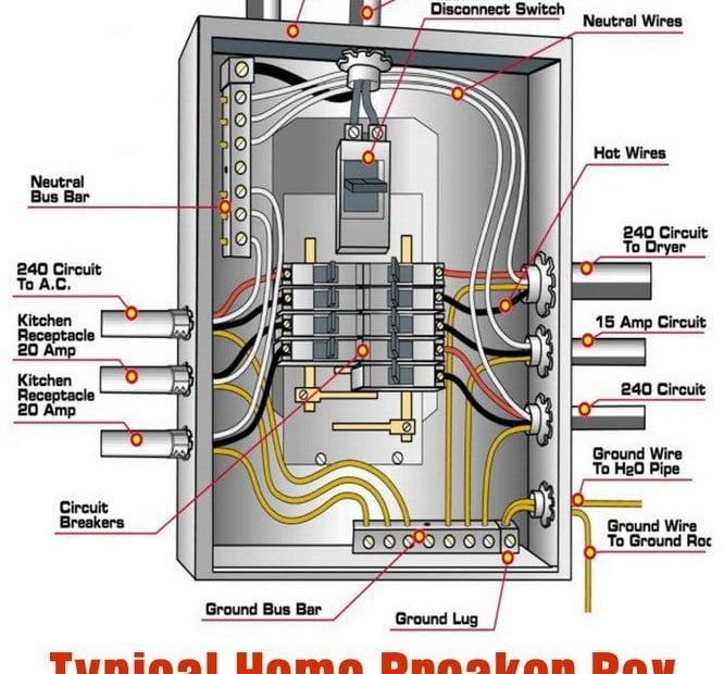
The main components of a main breaker box wiring diagram include the individual breaker switches, the main breaker switch, and the neutral and ground bars. Each circuit breaker switch controls a specific electrical circuit in the home, and is rated for a specific amperage. The main breaker switch, on the other hand, controls the entire electrical supply to the home, and is also rated for a specific amperage. The neutral and ground bars provide a safe path for any excess electrical current to flow to a ground source, which prevents the electrical system from becoming overloaded or damaged.
How to Read and Interpret the Main Breaker Box Wiring Diagram
To read and interpret a main breaker box wiring diagram, it is essential to understand the symbols and labels used. Breaker switches are typically labeled with their amperage rating, and may be color-coded based on the type of circuit they control. Ground wires are usually green or bare, while neutral wires are white or gray. Hot wires, which carry the electrical current, are usually black or red. The diagram may also indicate where each wire is connected, and may include any fusing or surge protection devices that are present.
Common Issues with Main Breaker Box Wiring Diagrams
While a main breaker box wiring diagram is an invaluable tool, there are some common issues that may arise. For example, it may be difficult to determine the exact location of a faulty circuit or component, or the diagram may not accurately reflect the current layout of the wiring. In some cases, the wiring may be damaged or improperly installed, which can pose a serious safety hazard.
Steps to Troubleshoot Main Breaker Box Wiring Diagram Problems
To troubleshoot any problems with a main breaker box wiring diagram, it is essential to first ensure that the electrical supply to the home is turned off. Then, carefully examine the wiring connections and components, looking for any signs of damage or wear. If necessary, test each circuit with a multimeter or other electrical testing tool, and make any necessary repairs or replacements. Always follow proper safety precautions when working with electrical wiring, and consult a licensed electrician if you are unsure or uncomfortable with any aspect of the job.
In conclusion, a main breaker box wiring diagram is a critical tool for anyone dealing with electrical wiring in a home or building. By understanding the components, symbols, and labels used, and by following proper safety procedures, homeowners and electricians alike can ensure that any repairs or upgrades are done safely and effectively. Whether you are working with a single phase breaker box wiring diagram, a 200 amp breaker box wiring diagram, an electrical panel wiring diagram, an Eaton breaker box wiring diagram, or any other type of diagram, always remember to put safety first.
Keywords searched by users: main breaker box wiring diagram single phase breaker box wiring diagram, 200 amp breaker box wiring diagram, electrical panel wiring diagram, eaton breaker box wiring diagram, how to wire 240v single phase breaker, main electrical panel diagram, simple control panel wiring diagram, 100 amp breaker box wiring diagram
Tag: Share 92 – main breaker box wiring diagram
Main electrical panel explained – Load center – service panel
See more here: cungcaphangchinhhang.com
Article link: main breaker box wiring diagram.
Learn more about the topic main breaker box wiring diagram.
- Understanding Your Home’s Main Circuit Breaker | Happy Hiller
- Wiring a Breaker Box – Electrical Panel – Bob Vila
- Line Side Tap vs. Load Side Tap: Everything You Need To Know
- Schematic vs. Wiring Diagrams – Basic Motor Control
- How to Wire 120V & 240V Main Panel? Breaker Box …
- Circuit Breaker Wiring Diagrams – Do-It-Yourself-Help.com
- 100 Amp Sub Panel Wiring Diagram – Circuits Gallery
- Circuit Breaker Panel Diagram | EdrawMax Template
- Wiring a Breaker Box – Electrical Panel – Bob Vila
- Electrical Panel Wiring Diagram – SolisPLC
Categories: https://cungcaphangchinhhang.com/category/img blog